PocketBeagle High Level Specification#
This section provides the high level specification of PocketBeagle.
Block Diagram#
Figure 22 below is the high level block diagram of PocketBeagle.
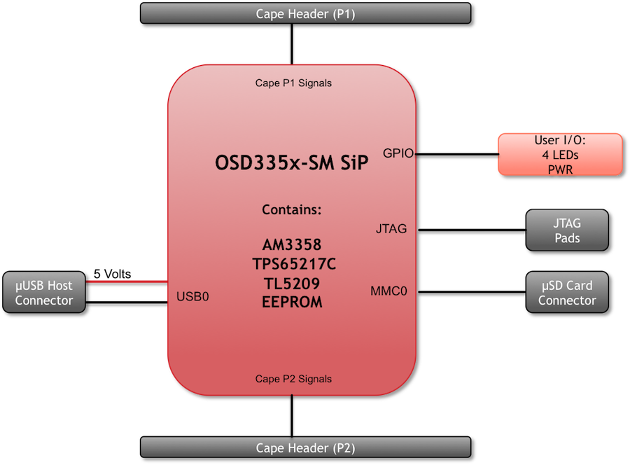
Fig. 362 PocketBeagle Key Components#
System in Package (SiP)#
The OSD335x-SM Block Diagram is detailed in Figure 23 below. More information, including design resources are available on the ‘Octavo Systems Website’
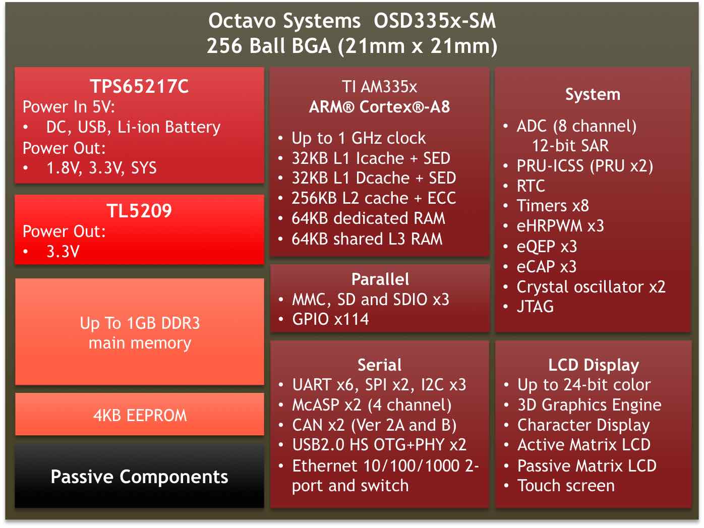
Fig. 363 OSD335x SIP Block Diagram#
Note: PocketBeagle utilizes the 512MB DDR3 memory size version of the OSD335x-SM A few of the features of the OSD335x-SM SiP may not be available on PocketBeagle headers. Please check Section 7 for the P1 and P2 header pin tables.
Connectivity#
Expansion Headers#
PocketBeagle gives access to a large number of peripheral functions and GPIO via 2 dual rail expansion headers. With 36 pins each, the headers have been left unpopulated to enable users to choose the header connector orientation or add-on board / cape connector style. Pins are clearly marked on the bottom of the board with additional pin configurations available through software settings. Detailed information is available in Section 7.
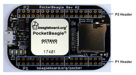
Fig. 364 PocketBeagle Expansion Headers#
microSD Connector#
The board is equipped with a single microSD connector to act as the primary boot source for the board. Just about any microSD card you have will work, we commonly find 4G to be suitable.
When plugging in the SD card, the writing on the card should be up. Align the card with the connector and push to insert. Then release. There should be a click and the card will start to eject slightly, but it then should latch into the connector. To eject the card, push the SD card in and then remove your finger. The SD card will be ejected from the connector. Do not pull the SD card out or you could damage the connector.
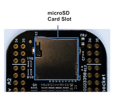
Fig. 365 microSD Connector#
USB 2.0 Connector#
The board has a microUSB connector that is USB 2.0 HS compatible that connects the USB0 port to the SiP. Generally this port is used as a client USB port connected to a power source, such as your PC, to power the board. If you would like to use this port in host mode you will need to supply power for peripherals via Header P1 pin 7 (USB1.VIN) or through a powered USB Hub. Additionally, in the USB host configuration, you will need to power the board through Header P1 pin 1 (VIN) or Header P1 pin 7 (USB1.VIN) or Header P2 pin 14 (BAT.VIN)
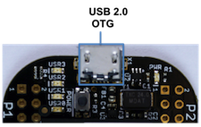
Fig. 366 USB 2.0 Connector#
Boot Modes#
There are three boot modes:
SD Boot: MicroSD connector acts as the primary boot source for the board. This is described in Section 3.
USB Boot: This mode supports booting over the USB port. More information can be found in the project called “BeagleBoot” This project ported the BeagleBone bootloader server BBBlfs(currently written in c) to JavaScript(node.js) and make a cross platform GUI (using electron framework) flashing tool utilizing the etcher.io project. This will allow a single code base for a cross platform tool. For more information on BeagleBoot, see the BeagleBoot Project Page.
Serial Boot: This mode will use the serial port to allow downloading of the software. A separate USB to TTL level serial UART converter cable is required or you can connect one of the Mikroelektronika FTDI Click Boards to use this method. The UART pins on PocketBeagle’s expansion headers support the interface. For more information regarding the pins on the expansion headers and various modes, see Section 7.
H eader.Pin |
S ilkscreen |
Proc Ball |
SiP Ball |
Pin Name (Mode 0) |
P1.22 |
GND |
GND |
||
P1.30 |
U0_TX |
E16 |
B12 |
uart0_txd |
P1.32 |
U0_RX |
E15 |
A12 |
uart0_rxd |
If the Serial Boot is not in use, the UART0 pins can be used for Serial Debug. See Section 5.6 for more information.
Software to support USB and serial boot modes is not provided by beagleboard.org. Please contact TI for support of this feature.
Power#
The board can be powered from three different sources:
A USB port on a PC.
A power supply with a USB connector.
Expansion Header pins.
Note
VIN-USB is directly shorted between the USB connector on PocketBeagle and USB1_VI on the expansion headers. You should only source power to the board over one of these and may optionally use the other as a power sink.
The tables below show the power related pins available on PocketBeagle’s Expansion Headers.
H eader.Pin |
S ilkscreen |
Proc Ball |
SiP Ball |
Pin Name (Mode 0) |
P1.01 |
VIN |
P10, R10, T10 |
VIN |
|
P1.07 |
USB1_VI |
P9, R9, T9 |
VIN-USB |
|
P2.14 |
BAT_+ |
P8, R8, T8 |
VIN-BAT |
H eader.Pin |
S ilkscreen |
Proc Ball |
SiP Ball |
Pin Name (Mode 0) |
P1.14 |
+3.3V |
F6, F7, G6, G7 |
VOUT-3.3V |
|
P1.24 |
VOUT |
K6, K7, L6, L7 |
VOUT-5V |
|
P2.13 |
VOUT |
K6, K7, L6, L7 |
VOUT-5V |
|
P2.23 |
+3.3V |
F6, F7, G6, G7 |
VOUT-3.3V |
H eader.Pin |
S ilkscreen |
Proc Ball |
SiP Ball |
Pin Name (Mode 0) |
P1.15 |
USB1_GND |
GND |
||
P1.16 |
GND |
GND |
||
P1.22 |
GND |
GND |
||
P2.15 |
GND |
GND |
||
P2.21 |
GND |
GND |
Note
A comprehensive tutorial for Power Inputs and Outputs for the OSD335x System in Package is available in the ‘Tutorial Series’ on the Octavo Systems website.
JTAG Pads#
Pads for an optional connection to a JTAG emulator has been provided on the back of PocketBeagle. More information about JTAG emulation can be found on the TI website - ‘Entry-level debug through full-capability development’
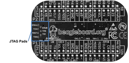
Fig. 367 JTAG Pad Connections#
Serial Debug Port#
Serial debug is provided via UART0 on the processor. See Section 5.3.4 for the Header Pin table. Signals supported are TX and RX. None of the handshake signals (CTS/RTS) are supported. A separate USB to TTL level serial UART converter cable is required or you can connect one of the Mikroelektronika FTDI Click Boards to use this method.
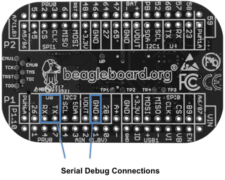
If serial boot is not used, the UART0 can be used to view boot messages during startup and can provide access to a console using a terminal access program like Putty. To view the boot messages or use the console the UART should be set to a baud rate of 115200 and use 8 bits for data, no parity bit and 1 stop bit (8N1).
